About Us
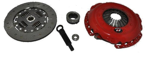
EFI Motorsport is a company dedicated to providing quality upgrade parts, hardware, software, and service for a range of European vehicles.
Our online catalog represents only a small fraction of the items we carry. If you're looking for something and cant find it on our website please give us a call or send us an email, we're looking forward to helping with your project.
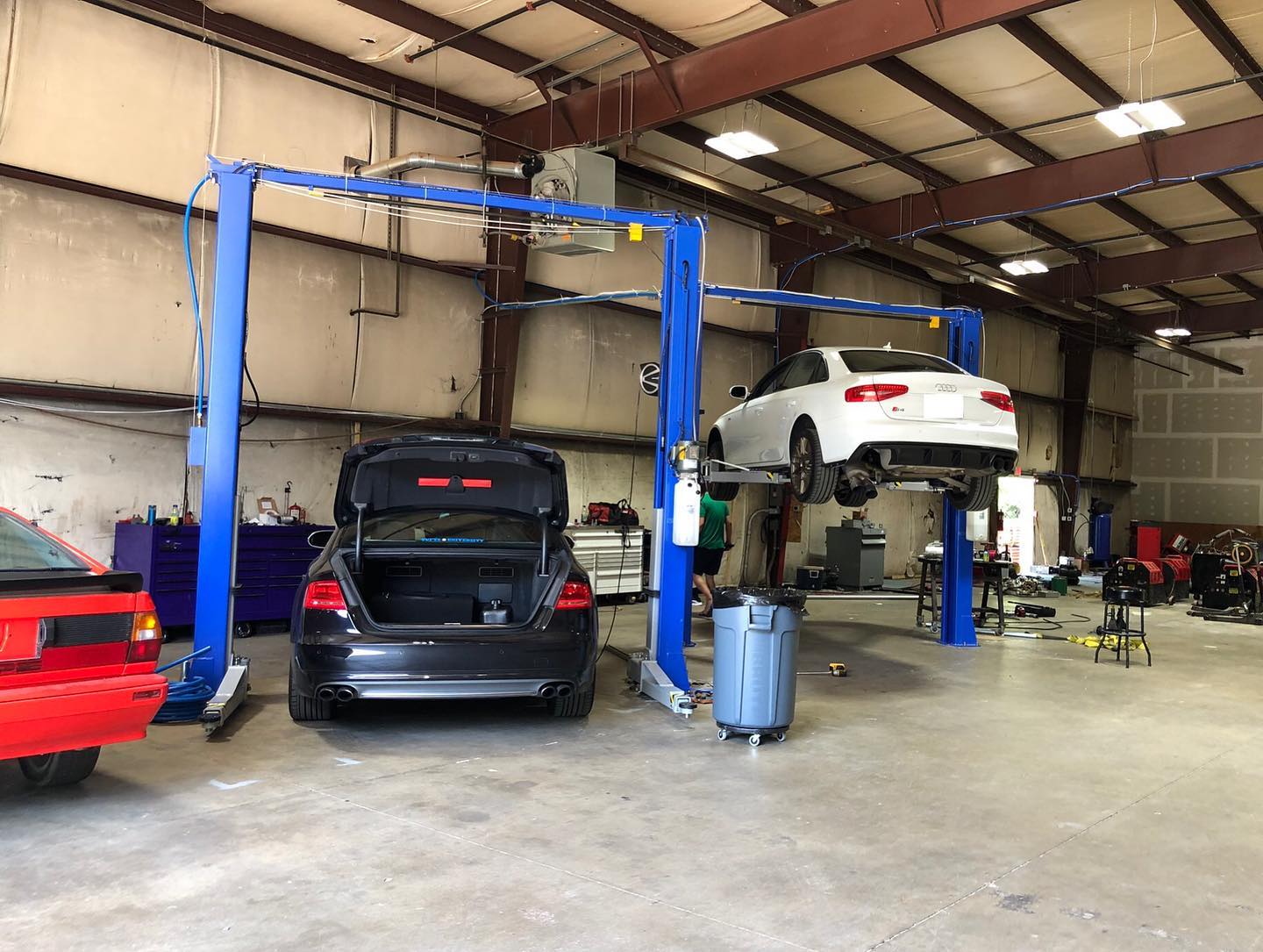
We are also a full service automotive center for those of us local to our Somersworth, NH location. contact us with your needs!